sgCBRep
In the sgCore library all 3D solids are stored in the form of the polygonal surface representation - boundary representation – BRep. This representation defines a solid implicitly by describing its boundary surface. Each surface is approximated by a set of faces. The fragmentation is performed in such a way that each face has a compact mathematical representation.
Face boundaries are represented by edges. Edges are selected like faces in such a way that each edge has a compact mathematical description. A part of the curve that forms an edge is ended by vertexes. It's necessary to introduce such a term as cycle (the description of each face contour) because every face can be a non-convex polygon with any number of holes.
A surface model which has only flat faces is called a polygonal model – this type of description is used in sgCore. So, every face is a polygon which consists of the vertex coordinates sequence. An object consists of the set of faces.
SgCore also introduces such a term as BRep piece. A BRep piece is a piece of simply connected boundary body surface.
This term has been introduced to accelerate the work of some algorithms (such as Boolean operations). Each BRepPiece has a limitary dimensional parallelogram. It was designed to avoid passes of each BRep pieces face in the cycles. All BRep pieces connected together form a full BRep.
Let's look at the BRep description on the solid example created by extruding a flat non-convex contour with one hole. This BRep is divided into 4 pieces – 2 bases, a side face and a hole surface.
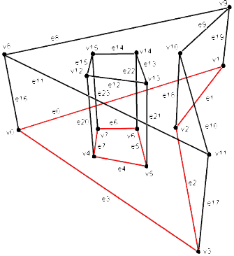
Below you can see the table of the vertex and edge descriptions for all BRep pieces.
The vertex coordinate recurrence can be avoided by grouping the vertex coordinates in a separate array. In this case vertex coordinate indexes in the array (not the vertex coordinates themselves) get associated with faces and edges. In this case (see the picture) we have:
BRep Piece number and description |
Vertexes |
Edges |
|||||||||
Name |
Number |
X |
Y |
Z |
Name |
Number |
Begin |
End |
|||
0 Bottom base |
v0 v1 v2 v3 v4 v5 v6 v7 |
0 1 2 3 4 5 6 7 |
-2.0 1.0 0.0 0.0 -1.0 -0.4 -0.5 -1.0 |
0.0 2.0 0.0 -2.0 -0.6 -0.8 0.0 0.0 |
0.0 0.0 0.0 0.0 0.0 0.0 0.0 0.0 |
e0 e1 e2 e3 e4 e5 e6 e7 |
0 1 2 3 4 5 6 7 |
0 1 2 3 4 5 6 7 |
1 2 3 0 5 6 7 4 |
||
1 Side face |
v0 v8 v1 v9 v2 v10 v3 v11 |
0 1 2 3 4 5 6 7 |
-2.0 -2.0 1.0 1.0 0.0 0.0 0.0 0.0 |
0.0 0.0 2.0 2.0 0.0 0.0 -2.0 -2.0 |
0.0 1.0 0.0 1.0 0.0 1.0 0.0
|
e0 e16 e8 e1 e19 e9 e2 e18 e10 e3 e17 e11 |
0 1 2 3 4 5 6 7 8 9 10 11 |
0 0 1 2 2 3 4 4 5 6 6 7 |
2 1 3 4 3 5 6 5 7 0 7 1 |
||
2 Top base
|
v8 v9 v10 v11 v12 v13 v14 v15 |
0 1 2 3 4 5 6 7 |
-2.0 1.0 0.0 0.0 -1.0 -0.4 -0.5 -1.0 |
0.0 2.0 0.0 -2.0 -0.6 -0.8 0.0 0.0
|
1.0 1.0 1.0 1.0 1.0 1.0 1.0 1.0
|
e8 e9 e10 e11 e12 e13 e14 e15
|
0 1 2 3 4 5 6 7
|
0 1 2 3 4 5 6 7
|
1 2 3 0 5 6 7 4
|
||
3 Hole surface |
v4 v12 v5 v13 v6 v14 v7 v15 |
0 1 2 3 4 5 6 7 |
-1.0 -1.0 -0.4 -0.4 -0.5 -0.5 -1.0 -1.0 |
-0.6 -0.6 -0.8 -0.8 0.0 0.0 0.0 0.0
|
0.0 1.0 0.0 1.0 0.0 1.0 0.0 1.0 |
e4 e20 e12 e5 e21 e13 e6 e22 e14 e7 e23 e15 |
0 1 2 3 4 5 6 7 8 9 10 11 |
0 0 1 2 2 3 4 4 5 6 6 7
|
2 1 3 4 3 5 6 5 7 0 7 1
|
||
A face is represented by a set of edges. An index of the initial face edge is set and the cycle structure determines each next face edge. In this way the outer contours of the faces and their holes can be set.